Flags
Components and operation - Conditional and unconditional jumps - Calculation of Flags N, V, Z and C - The Carry and the H and ALU registers - Schematic - Differences between NQSAP and BEAM Flag modules - Useful links

Many times, while analyzing the NQSAP and reading Tom Nisbet’s documentation, I had found very ingenious ideas; some of these are found in the Flag module.

Schematic of Tom Nisbet’s Flag module, slightly modified for the sole purpose of improving its readability.
The NQSAP Flag register emulates the 4 NVZC flags of the 6502:
- Negative (N)
- OVerflow (V)
- Zero (Z)
- Carry (C)
It is completely different from the simple Flag register of Ben Eater’s SAP-1 computer, in which a single 74LS173 D-type register stored only the 2 flags C and Z at the same time: instruction management required 4 sets of microcode, i.e. one for each combination of flag signals brought to the EEPROM inputs; each set of microcode was in fact developed “custom-made” to activate the correct output signals for managing C and/or Z. This is well explained in Ben Eater’s video Conditional jump instructions.
Tom’s approach was instead based on a logical verification performed in hardware: the microcode did not vary depending on the state of the flags, which were no longer directly connected to the ROM addressing lines that in turn activate different output signals based on the address/flag presented at the input!
Analyzing for example a conditional jump instruction linked to the Z flag, I found that:
- the microcode of the jump instruction activated a generic “Jump Enable” signal connected to pin 7 of the 74LS151 Data Selector/Multiplexer visible in the lower right of the general schematic;
- the selection of the flag to put at the output of the ‘151 depended on the encoding of the instruction being executed, since the 3 Select bits S2, S1 and S0 were directly connected to the Instruction Register, i.e. hardwired, in a similar manner to what was also done in the ALU module;

Instruction Register output toward the Flag module with highlight of the 3 selection bits of the conditional jump instruction.

Selection inputs of the conditional jump instruction of the Flag register and hardwired connection with the IR.
If for example a generic Jump on Zero instruction were encoded as 010 on the 3 signals S2, S1 and S0 shared between the Instruction Register (IR) and the Flag register, the following sequence would occur:
- input pin I2 of the ‘151 would be activated;
- in the presence of the Z flag, the output Q of the Flip-Flop connected to pin I2 would have logic value HI;
- the output of the ‘151 would enable the /PC-LOAD signal on the Program Counter (PC) to jump to the new address.
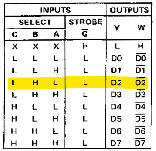
74LS151 Selector/Multiplexer function table with highlight of the hypothetical Jump on Zero instruction.
In other words: the conditional jump logic of the SAP-1 was implemented in the microcode, using ROM addressing lines. Since the NQSAP flags were instead implemented in hardware, there was no need to consume precious EEPROM addressing lines (and to double the microcode size with each addition of a flag).
The improvements deriving from this architecture are:
- possibility of setting flags individually as well;
- saving of EEPROM addressing lines;
- flag updates do not modify the EEPROM addresses in the middle of instruction execution and eliminate this possible cause of glitching.
Components and operation
A 74LS157 multiplexer (MUX) takes the values of flags V, Z and C as input, selecting their source:
-
from the bus; when the ‘157 reads from the bus, it is possible to load the flag registers by reading arbitrary values from the computer’s memory (or, more precisely, from the memory area used for the Stack), similarly to what is done by the 6502’s Pull Processor Status PLP instruction;
-
from a computation:
- V through a ‘151 Data Selector/Multiplexer that recreates the logical Overflow function by verifying a possible sign change in the result of addition or subtraction operations of signed numbers (Signed);
- Z Z as the result of the 74LS688 comparator;
- C through another ‘151 that selects the Carry source;
The FS control signal at LO level allows loading of Flags from the bus; conversely, loading of computed Flags requires FS to be active.
V, Z and C output from the ‘157 MUX are presented to 3 of the 4 Flip-Flops available in a pair of 74LS74.
The Negative flag is instead always read directly from line D7 of the bus and loaded onto the 4th Flip-Flop.
Four AND gates allow loading of the FFs in the presence of the clock signal and the simultaneous activation of the appropriate FN, FV, FZ and FC signals coming from the Control Logic (CL); it should be remembered that register loading is always performed at the Rising Edge of the Clock.
Each computer instruction, thanks to microcode customization, can set more than one flag at a time (as happens for example with ADC and SBC operations, which on the 6502 simultaneously affect all 4 NVZC flags).
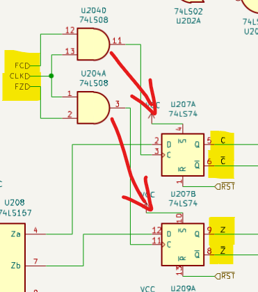
Loading of Flip-Flops C and Z with Clock AND FC / FZ signals.
-
Note that the FFs are never pre-set, therefore /Preset remains fixed at Vcc (and thus never active); there is instead a connection to the general reset signal of the computer (/RST).
-
The FF outputs are connected to a ‘151 to manage conditional jumps.
-
The C Flag is also exported toward the ‘181s and the H register of the ALU module; see the section The Carry and the H and ALU registers on this same page.
A 74LS245 bus transceiver finally allows exporting the 4 NVZC flags onto the bus to save them in memory, or more precisely in the Stack, similarly to what happens in the 6502 with the Push Processor Status (PHP) instruction.
It is interesting to note that the CLC, CLV and SEC instructions do not need dedicated CL signals to clear or set the C and V flags: the ALU is used to put 0x00 or 0xFF on the bus and only the flag of interest is modified by appropriately activating the FC or FV control signal.
Conditional and unconditional jumps
Every change of a flag in Ben Eater’s SAP-1 computer generated a change in the EEPROM addresses, so as to be able to activate appropriately different output signals as a consequence of the different combinations of flag states.
The NQSAP approach is very different, since all flag signals (present on the Q and /Q outputs of the ‘74 FFs) are presented to a ‘151; its function is to select one of the flags to put on its output to possibly allow the activation of the /PC-LOAD signal, which enables loading of the bus contents onto the Program Counter (and therefore jumps). It is in fact sufficient to load a new value into the Program Counter (PC) for it to become the new address from which the subsequent instructions of the program loaded in the computer’s memory will be fetched and executed.
How does the selection of the flag to bring to the Z output of the ‘151 occur? The signals IR-Q5 (S0), IR-Q6 (S1) and IR-Q7 (S2) coming from the IR select which of the inputs of the ‘151 (I0-I7) should be brought to the Z output, as seen previously in the function table of the 74LS151 Selector/Multiplexer. The signals IR-Q5, Q6 and Q7 are in fact hardwired with the IR: the branch instructions, each with its specific encoding, determine which input of the ‘151 will be activated and exposed at the output; depending on the state of the exposed flag, /PC-LOAD will possibly be active and the relative jump instruction can be executed.
Let us take as an example the BCS instruction (Branch on Carry Set) assuming that the previous instruction generated a Carry and that therefore the corresponding FF presents logic state HI on the Q output:

Branch on Carry Set instruction example.
-
the instruction will be encoded in the microcode so that S0, S1 and S2 select input I0, which is connected to the Carry FF:
- S0 = LO
- S1 = LO
- S2 = LO
-
since the Carry is active, the output of the NOR connected to the Z output is certainly LO (/PC-LOAD = NOT (1+x) = 0), therefore the value present on the bus is loaded into the PC (the /PC-LOAD signal is active LO).
One aspect that initially escaped my understanding was how it was possible to include branch instructions (8 combinations = 3 bits), ALU instructions (5 bits) and all other instructions (for example load, transfer) in just 8 bits: how was it possible to manage all combinations and build an instruction matrix? At the moment when I had to execute any other instruction, what would have happened in the management of relative jumps, given that they were directly a function of the encoding of the instruction currently being executed? Was there not a risk of executing an unwanted conditional jump if I had found myself for example in a situation where (as described just above) IR-Q5, Q6 and Q7 were LO and the Carry was active?
Later I had noticed that in the ‘151 responsible for flag selection there was also a JE Enable signal, present in the microcode of conditional jump instructions only, therefore:
-
if JE is HI and if the output of the selected FF is HI, the output of the ‘151 will itself be HI, allowing the loading of the Program Counter;
-
if JE is LO, the output of the ‘151 will be deactivated, therefore no load signal will be sent to the Program Counter.
Therefore the instructions — and only those — whose microcode included the JE signal were considered conditional jump instructions; all others ignored the jump, since the /PC-LOAD signal would never have been activated.
Tom pointed out that “this method simplifies the microcode, because all jump operations will use the same microcode”.
Why should all jump instructions be “the same”? The explanation, simple only after having understood it well, lies in the fact that the choice of the flag to use for the conditional jump no longer depends on the instruction’s microcode, but on the encoding of the instruction itself: being hardwired with the IR, the signals IR-Q5, Q6 and Q7 are automatically applied to the Select inputs of the ‘151; it is in the construction of the instruction set that one must take into account which encoding to associate with the various instructions BCS, BCC, BNE, BPL and so on. No variation is required in the microcode.
Let us take as a further example the BVC instruction (Branch on OVerflow Clear) assuming that there is no Overflow and that therefore the /V signal is active:

Branch on OVerflow Clear instruction example.
-
the instruction will need to be encoded in the microcode so that S0, S1 and S2 select input I5, which is connected to the /Q output of the Overflow FF:
- S0 = HI
- S1 = LO
- S2 = HI
Now taking into account the existence of the Jump Enable (JE) signal, highlighted in yellow, it emerges that the activation of /PC-LOAD and a consequent conditional execution of a jump determined by the possible absence of Overflow require an instruction:
- whose encoding leads to having S2/S1/S0 = 101 at the selection inputs of the ‘151, and
- whose microcode activates the JE signal.
At this point in the explanation it will have been noted that the ‘74 FFs expose the flags both in normal logic (Q) and in inverted logic (/Q): this is very convenient for determining the presence or absence of a given flag. Using another example, if the Carry were not present and one wished to execute a jump by verifying the condition “Carry not present” (Branch on Carry Clear, BCC), one can verify whether /Q is HI, so as to appropriately activate the /PC-LOAD jump signal.
The use of a NOR at the Z output of the ‘151 allows managing both conditional jumps (therefore to be validated with an appropriate logical check, i.e. that of the presence/absence of a given flag) and unconditional jumps:
-
In the case of a conditional jump (BCS, BVC, BEQ etc.), a positive verification of the presence/absence of the selected flag (normal or inverted) generates a HI output on the ‘151 → the NOR therefore presents LO output and activates the loading of the jump address onto the Program Counter. The D, X and Y registers page describes the calculation of the value to be inserted into the PC.
-
In the case of an unconditional jump (JMP, JSR), the microcode of the jump instruction activates /WP (in inverted logic) which in turn activates the loading onto the PC of the value present on the bus: (/PC-LOAD = NOT (x+1) = 0), therefore the PC loads its new value from the bus.
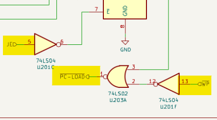
NOR for the activation of /PC-LOAD with conditional and unconditional jumps.
In conclusion, the microcode of jump instructions provides for:
- the activation of JE to execute conditional jumps;
- the activation of WP to execute unconditional jumps.
Calculation of Flags N, V, Z and C
Negative
As mentioned previously, the Negative flag is derived from the 7th bit of the bus, i.e. the MSB: the flag is managed on the D7 line of the bus since Signed numbers use precisely the Most Significant Bit (MSB) to indicate their sign. It is interesting to note that, since N is mapped on the bus and not directly on the ALU, it is possible to detect a Negative number also in contexts external to the ‘181s, for example in the result of a rotation performed with the Shift-Register or in a data transfer from one register to another: everything that passes through the bus can be subject to verification of its state as a positive or negative Signed number.
Zero
The Zero flag is active when the value present on the bus is zero; rather than using a series of NOR and AND logic gates to verify whether all lines are LO (as happened in the SAP), a single ‘688 comparator can perform the same function. Note that this flag too operates on the bus and not on the results of the ALU alone.
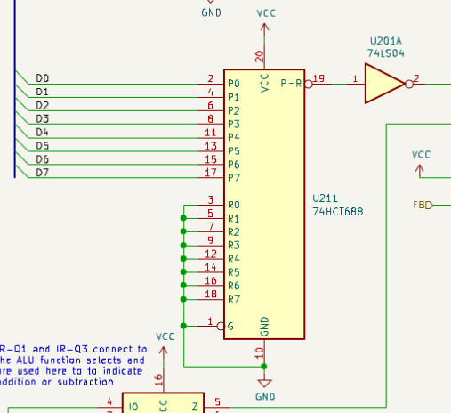
74LS688 comparator for zero state verification on the bus.
Overflow
The OVerflow flag is calculated using a ‘151 in the manner described in 74181 with V_Flag on the 6502.org website.
I had found the explanation very cryptic, or perhaps not exactly suited to non-experts, to the point of spending several tens of hours to fully understand what was stated by re-reading, searching for other sources, watching binary arithmetic videos, doing exercises on paper and on a spreadsheet.
Tom pointed out that the MSBs of the ALU operands H and B, together with the MSB resulting from the ALU operation, were used as inputs to verify the Overflow condition: I was beginning to realize that Overflow was actually a very simple and precise bit calculation.
Later I had understood that the Overflow calculation is strictly linked to the use of Signed numbers: these numbers are represented with Two’s Complement (2C), in which an MSB = LO indicates a positive number, while an MSB = HI indicates a negative number.
In one of the countless study and research sessions, I had finally come to understand that if in the addition of two signed numbers an unexpected sign change in the result is noticed, an Overflow situation occurs: the sign change is represented by a variation of the MSB of the result, something that an appropriately connected ‘151 allows to identify.
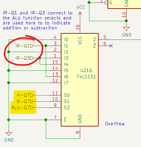
Use of a 74LS151 for Overflow calculation with highlight of the MSBs of H, B and the ALU and the operation selection inputs IR-Q1 and IR-Q3.
To identify the execution of an addition or subtraction operation and therefore select which should be the correct input of the ‘151 to activate, two of the ALU operation selection lines are used, in particular:
| IR-Q1 | IR-Q3 | Operation |
|---|---|---|
| HI | LO | Subtraction |
| LO | HI | Addition |
I will briefly anticipate another aspect described in greater detail in the section dedicated to unsigned and signed numbers: in a byte 256 combinations are possible; in the case of unsigned numbers it is possible to count from 0 to 255. In the case of Signed numbers, the positive numbers from 0 to 127 have an equal correspondence with the unsigned numbers from 0 to 127, while the signed numbers from -128 to -1 are paired with the unsigned numbers from 128 to 255.
On the page dedicated to Binary Arithmetic there is also an in-depth analysis of Overflow and the use of a 74LS151 for managing conditional jumps.
Carry
The Flag register includes a register dedicated to the Carry. The NQSAP includes several operations that can generate a Carry:
- for arithmetic calculations the Carry corresponds to the Carry Output of the ‘181 ALU;
- for shift and rotate operations, the Carry is taken from the Least Significant Bit (LSB) (pin H-Q0) or from the MSB (pin H-Q7) of the H register.
The use of another ‘151 represents the most efficient system for selecting the Carry source. Depending on the instruction being executed, the microcode of that instruction will in fact appropriately activate the C0 and C1 signals:
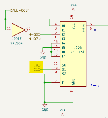
Use of a 74LS151 for selecting the Carry to be stored in the Carry flag.
| C1 | C0 | Carry selection |
|---|---|---|
| LO | LO | From the ALU Carry Output (not inverted*) |
| LO | HI | From the ALU Carry Output (inverted**) |
| HI | LO | From the MSB (H-Q7) of register H |
| HI | HI | From the LSB (H-Q0) of register H |
-
* this configuration is not used
-
** As already discussed on the ALU page, the ‘181 Carry works in negative logic, therefore a signal C = LO indicates that the Carry is present; it goes without saying that to record the state of the Carry in positive logic on the C Flag register it is necessary to invert the input signal.
The Carry and the H and ALU registers
In addition to being used for conditional jumps, the Carry is clearly used in the ALU module to perform arithmetic operations (‘181) and shift and rotate operations (‘194).
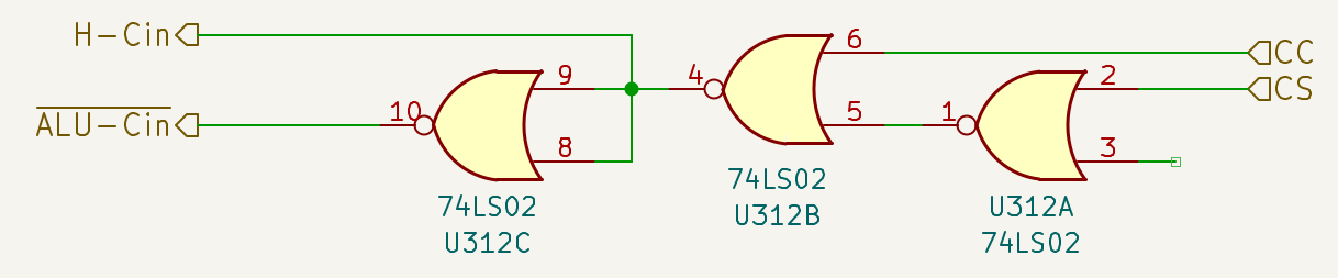
Selection of the Carry to pass to the Carry Input of H and the ‘181s of the ALU module.
The appropriate programming of the CC (Carry Clear) and CS (Carry Set) signals in the microcode can pass to the Carry Input of H (H-Cin) and the ‘181s (ALU-Cin):
- a hard-coded value of 0
- a hard-coded value of 1
- the actual value present in the C Flag register
The need to send to the ALU module not only the actual value of the C flag, but also predefined values of 0 or 1, depends on two factors:
- Some arithmetic operations of the ‘181 require a specific Carry state: for example the A Minus 1 and A Plus B operations require the absence of input Carry, while the A Plus 1 and A Minus B operations require its presence; the signal sent to the ‘181s is ALU-Cin.
- The ASL and LSR instructions (Arithmetic Shift Left and Logical Shift Right) performed by the ‘194 require the insertion of a 0 respectively into the LSB and MSB of H; the signal sent to the ‘194s is H-Cin.
| CS | CC | Carry presented to the ALU module |
|---|---|---|
| LO | LO | Value present in the C Flag register |
| LO | HI | LO |
| HI | LO | HI |
| HI | HI | Not used |
The negation of the signal sent to the Carry Input of the ‘181 derives from the fact that the configuration used by the ALU (active-high logic, “Active-High data”) requires an inverted Carry In signal.
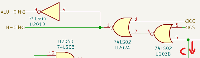
Note that the Truth Table would require the components highlighted in the following schematic, but the application of De Morgan’s laws allows the simplification subsequently used in the schematic adopted in the NQSAP and the BEAM.
Original schematic for implementation of the Carry selection Truth Table.
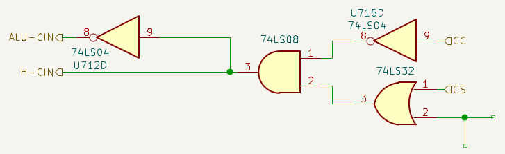
Revised schematic with the application of De Morgan’s theorem.
Schematic

Schematic of the BEAM computer Flag module.
Differences between NQSAP and BEAM Flag modules
The Flag module of the BEAM computer is substantially a copy of the Flag module of the NQSAP computer; with my knowledge I would not have been able to develop a better version of it, but the fact of having perfectly understood both its operation and its integration with the other computer modules was an excellent lesson.
Useful links
-
Ben Eater’s videos CPU flags register and Conditional jump instructions, which explain the construction of the Flag module and the necessary microcode modifications for managing conditional jump instructions. The difference will be noted with the NQSAP approach, which does not require ad-hoc microcode for each flag and does not need dedicated EEPROM addressing lines.
-
Tom notes that he took inspiration from the Reddit thread How to add a decremental and incremental circuit to the ALU ? for the idea of driving the loading of the Program Counter from the Flag register rather than managing them with multiple copies of the microcode as happened on Ben Eater’s SAP-1.
-
Furthermore, the inspiration for the implementation of the V Flag also derives from another Reddit thread, Question for all 74ls181 alu people; in particular, user SaltPeppah suggested the use of the 74LS151, indicating the link mentioned in the Overflow section of this page and in the Overflow in-depth section of the page dedicated to binary arithmetic, where the topic is covered extensively.
-
Tom also noted the approach of the thread Opcodes and Flag decoding circuit for executing conditional jumps in hardware. Instead of driving the LOAD line of the Program Counter, the circuit of the thread’s author is located between the IR and the EEPROM and conditionally forces a NOP or JMP instruction depending on the state of the flags. The opcodes of jump instructions are arranged so that the flag of interest can be determined by the bits output from the IR. An interesting concept, but Tom had already implemented a similar functionality with the ALU selection lines hardwired to the IR, a method also used in the management of conditional jumps.